
Display Cover Glass: Materials & Processes Explained
Table of Contents
The Function and Structure of CG
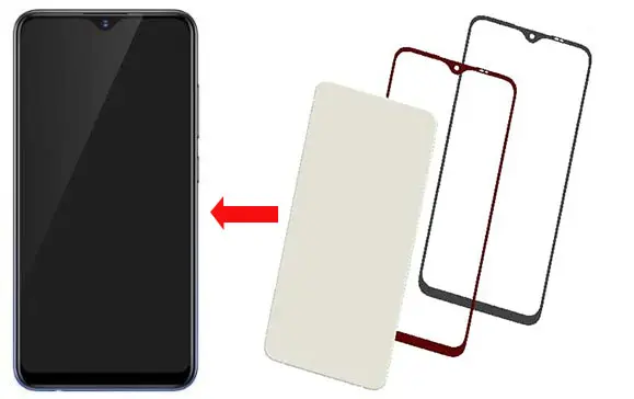
1.1 The Role and Composition of CG
The Role of CG: CG is the abbreviation for Cover Glass, and it has two main functions:
-
To protect the TFT-LCD display module/AMOLED display module.
-
To beautify the appearance and decorate the glass by screen printing different colors.
The Composition of CG: CG is mainly composed of tempered glass and ink. The ink includes main ink, bottom ink, IR ink, and character ink. The CG for mobile phones is often coated with an AF film (anti-fingerprint film) on its surface, which provides scratch resistance, improves a smooth and pleasant touch, and makes it feel slick.
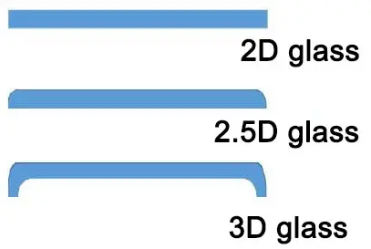
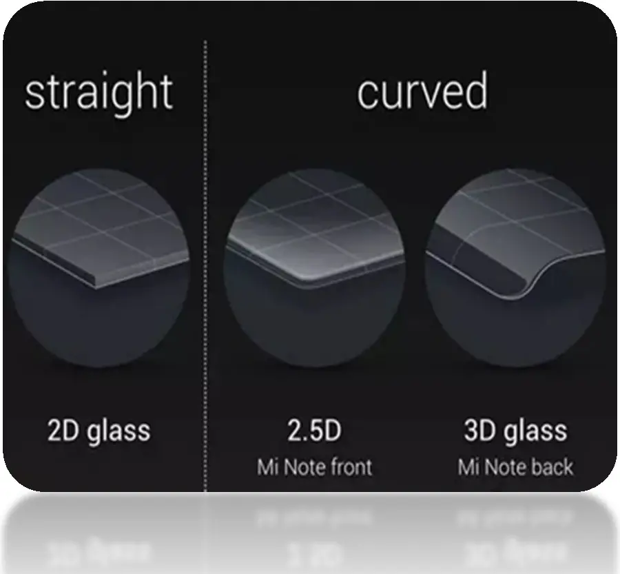
1.2 The Structure of CG (Cover Glass)
CG’s structure is categorized into 2D, 2.5D, and 3D glass. Currently, mobile phones and wearable products primarily use 2D, 2.5D, and 3D glass , while tablets and notebooks mainly use 2D glass.
2D Glass: Both the ink side and the non-ink side are completely flat with no curved design.
2.5D Glass: The ink side is flat, but the edge of the non-ink side has a curved design.
3D Glass: Both the ink and non-ink sides feature a curved design. Some have curved edges, while others are entirely curved.
Selection of Main Materials for CG
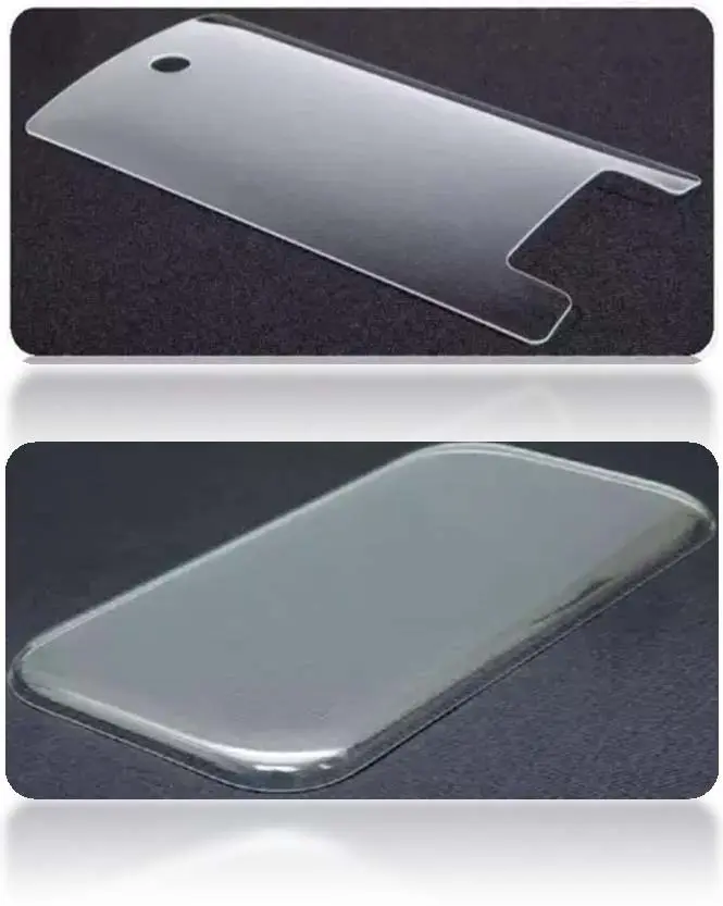
Table: Comparison of Soda-lime Glass vs. Aluminosilicate Glass (CG Cover Glass Materials)
| Item / Property | Soda-lime Glass (Na-Ca) | Aluminosilicate Glass (Al-Si) |
|---|---|---|
| Main Composition | SiO₂ + Na₂O + CaO | SiO₂ + Al₂O₃ + K⁺ ion exchange |
| Manufacturing Process | Float process | Float or Overflow (down-draw) |
| Density | ~2.5 g/cm³ | ~2.4–2.5 g/cm³ |
| Hardness | ~5–6 Mohs | ~6–7 Mohs |
| Strength (CS after chemical tempering) | ~300–500 MPa | ≥650–800 MPa |
| Depth of Compressive Layer (DOL) | ~10–20 µm | ≥30–50 µm |
| Optical Properties | Good transparency, but higher birefringence | Excellent transparency, lower photoelastic coefficient |
| Scratch Resistance | Low to medium | High |
| Drop Resistance | Poor (easy to crack) | Excellent (widely used in smartphones) |
| Thickness Range | Common: 0.7–1.1 mm | Wide range: 0.3–1.3 mm |
| Cost | Low, economical | Higher, but justified for performance |
| Typical Applications | Low-end devices, small displays, protective panels | Smartphones, tablets, automotive displays, high-end devices |
Table 2.2 One-Stage Chemically Strengthened Glass (Examples)
| Brand / Manufacturer | Model | Glass Category | Forming Process | Refractive Index (n) | Photoelastic Coefficient | Surface Stress (CS, MPa) | Depth of Layer (DOL, µm) | Central Tension (CT, MPa) | Notes |
|---|---|---|---|---|---|---|---|---|---|
| AGC (Japan) | AS2 | Soda-lime glass | Float | 1.517 | 27.0 | ≥550 | 10–17 | – | Common thickness 0.7 mm |
| Longji/Longwei (China) | DT-HW (Gen1) | Aluminosilicate | Float | 1.51 | 28.3 | ≥650 | ≥25–≥38 | ≤66–≤35 | Thickness 0.5–1.1 mm |
| Longji/Longwei (China) | DT-X (Gen2) | Aluminosilicate | Float | 1.50 | 29.9 | ≥750–≥800 | ≥35–≥40 | ≤77–≤67 | Thickness 0.5–0.7 mm |
| Longji/Longwei (China) | DT-Pro (Gen3) | Aluminosilicate | Float | 1.51 | 28.4 | ≥800 | ≥30–≥35 | ≤85–≤55 | Thickness 0.5–1.1 mm |
| CSG (China) | NBO-A (High-Alumina) | Aluminosilicate | Float | 1.51 | 27.5 | ≥700 | ≥40 | ≤52 | Example thickness 0.9 mm |
| Rainbow (China) | CG-01 | Aluminosilicate | Overflow (Down-draw) | 1.51 | 29.0 | ≥700 | ≥35 | ≤67 | Example thickness 0.8 mm |
| Corning (USA) | Gorilla Glass 3 (2320) | Aluminosilicate | Overflow | 1.51 | 31.9 | ≥750–≥775 | ≥35–≥45 | ≤82–≤45 | Thickness 0.5–1.1 mm |
| NEG (Japan) | T2X-1 | Aluminosilicate | Overflow | 1.50 | 29.5 | ≥700–≥750 | ≥35–≥40 | ≤80–≤40 | Thickness 0.5–1.1 mm |
| Xuhong/Panda (China) | MN228 (Panda) | Aluminosilicate | Float | 1.515 | 27.2 | ≥650–≥700 | ≥35–≥40 | ≤77–≤40 | Thickness 0.5–1.1 mm |
Table 2.3 Two-Stage Chemically Strengthened Glass (Examples)
| Brand / Manufacturer | Model | Glass Category | Forming Process | Refractive Index (n) | Photoelastic Coefficient | Surface Stress (CS, MPa) | Depth of Layer (DOL, µm) | Notes |
|---|---|---|---|---|---|---|---|---|
| Xuhong Optoelectronics (Xianning, China) | KK6 (Nanguang 2-stage) | Aluminosilicate | Float | 1.525–1.548 | 27.2–29.6 | ≥500 | – | Thickness 0.55–0.8 mm |
| Xuhong Optoelectronics (China) | Panda-1681 | Aluminosilicate | Float | 1.52 | 29.0 | ≥500 | – | Thickness 0.55–0.8 mm |
| Schott (Germany) | Xensation 3D | Aluminosilicate | Float | 1.525 (SLP) / 1.548 (FSM) | 27.2 / 30.0 | Na+ ≥100 (µm), K+ ≥600 (≥3.8 µm) | ≥100 µm | Curved glass applications |
| Corning (USA) | Gorilla Glass 5 (7321) | Aluminosilicate | Overflow | 1.51 | 30.1 | ≥550 | – | Thickness 0.4–1.3 mm |
Table 2.4 Ink Selection
| Brand | Ink Type | Model |
|---|---|---|
| Meilihua | Main Black Ink | EM-5002HB |
| Cicolor | Main Black Ink | CL04-EM-2020 |
| Cicolor | Main Black Ink | CL04-EM-0112B |
| Cicolor | Main Black Ink | CL04-GLN-0023 |
| JiaMei | Back Black Ink | CML-3598M |
| Cicolor | Back Black Ink | CL04-EM-0105 |
| Cicolor | Back Black Ink | CL04-EM-0112B (+12% matte) |
| Cicolor | Back Black Ink | EM10707 |
| Cicolor | Back Black Ink | CL04-EM-1077 |
| Carpoly | Back Black Ink | 84-K1032B |
| Boralay | Back Black Ink | PR-1075-5 |
Table 2.5 IR Ink & AF Coating
| Category | Brand | Model |
|---|---|---|
| IR Ink | Seiko | 1400N-1301-0082C |
| IR Ink | Seiko | 1400N-1807-3004C |
| IR Ink | Seiko | 1809-1063C + 1400N-1807-3004C |
| IR Ink | Seiko | 1810-2054C |
| IR Ink | Seiko | HF-1400N |
| IR Ink | Seiko | 1400N-177585 |
| IR Ink | Seiko | 1807-3021C |
| IR Ink | Seiko | 1808-3019C |
| AF Coating (Vacuum) | Daikin | UD509 (pill) / PAF217E |
| AF Coating (Vacuum) | Doen | PAF218C |
| AF Coating (Spray) | Daikin | ST-12 (liquid) / X10 / X12 |
| AF Coating (Spray) | Doen | SAH002 |
| Protection Film | Lanqing | LK-611P (0.05 mm) |
| Protection Film | Yongdahui | YDH-200 (0.05 mm) |
Description of CG Processing Procedures and Introduction to Main Procedures
3.1 Description of CG Processing Steps
This flowchart outlines the key stages in the manufacturing of cover glass:
-
-
Blanking (Raw glass is cut to a rough size.)
-
CNC Machining (The glass is precision-machined to its final shape, including holes and grooves.)
-
Polishing (Includes Side Edge and 2.5D Polishing) (The edges and surface of the glass are polished to remove scratches and improve smoothness.)
-
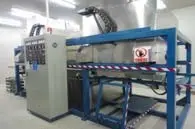
Ultrasonic Cleaning (The glass is thoroughly cleaned to remove contaminants.)
-
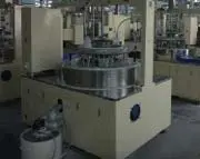
Tempering (The glass is strengthened through an ion exchange process in a chemical bath.)
-
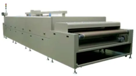
Screen Printing (Ink is applied to the glass to create patterns, colors, and logos.)
-
Baking (The ink is cured onto the glass.)
-
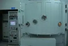
AF Coating (An anti-fingerprint film is applied to the surface of the glass.)
-
Final Inspection (The finished product undergoes a final quality check.)
3.2 Introduction to CG Raw Material Forming Methods: Float & Overflow Downdraw Process
Float Process
After the glass frit is melted in a furnace to form a glass liquid, it passes through a pipe where vertical baffles control the amount of glass liquid flowing into a molten tin float bath. When the homogeneous glass liquid flows into the tin-filled float chamber, it expands into a glass ribbon of a certain width. This ribbon is then horizontally drawn and gradually cooled before being pulled out of the liquid tin bath for annealing and cutting. 1
Overflow Downdraw Process
Raw materials such as specially formulated quartz sand and alumina are melted in a furnace and then a muffle furnace. The resulting glass liquid is transported through a pipeline into the groove of an overflow channel. When the glass liquid fills this groove, it overflows from the top and splits into two streams that flow down the sides of the channel. These two streams then merge at the bottom to form a single thin glass sheet. This sheet is then continuously drawn vertically for annealing and cutting. 2
Comparison of Advantages and Disadvantages
Glass produced by the overflow downdraw process has no front or back side, has better flatness, and less warping. Glass made by the float process, however, has different front and back sides (a tin side and a non-tin side), and has poorer flatness and more warping. 3
3.3 Introduction to Main CG Processing Steps
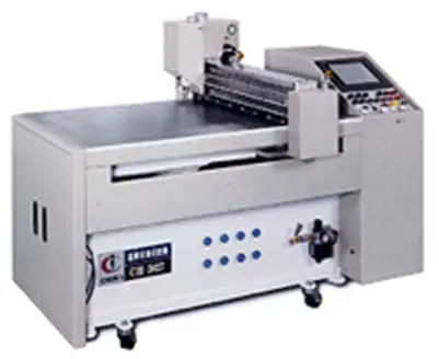
Blanking
-
Process: A protective film is applied to one side of the glass. A diamond cutting wheel is used to perform a straight cut. The blanked size is typically 0.3-0.8mm larger per side than the final product’s outer dimensions.
-
Equipment: Blanking machine, glass, protective film or spray film, cutting wheel, and material tray.
-
Parameters: Machine air pressure: 0.4-0.9MPa. Cutting pressure: 450-920 HP.
-
Process Capability: Dimensional tolerance: ±0.10 or ±0.15mm.
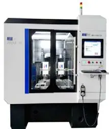
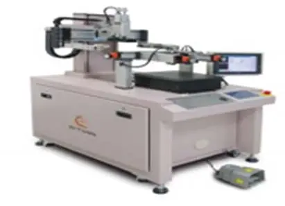
CNC Machining
-
Process: A precision engraving machine and grinding wheel head are used to grind the blanked glass pieces to remove excess material, and to create holes, grooves, and edges to form the final product’s shape.
-
Equipment: Precision engraving machine, grinding heads, cutting fluid, acrylic sheets, milling cutters, cleaning racks, and jigs.
-
Process Capability: Dimensional tolerance: ±0.03mm. Minimum through-hole: 1.0mm.
Side Edge Polishing
-
Process: The four sides of the CG (straight sections) are polished to repair the glass edges, reducing the chance of breakage during drops or ball-drop tests.
-
Note: The polishing brushes are generally hog bristle, and the polishing liquid concentration and particle size vary little among manufacturers.
2.5D Polishing
-
Process: Removes surface scratches and improves smoothness. The glass edge is polished at high speed with a felt pad to achieve a smooth and bright finish.
-
Parameters: Machine air pressure: 0.6-0.8 MPa. Polishing powder concentration: 0.8-1.1 g/cm³. Polishing time: 10-20 min.
Tempering
-
Process: Glass is placed in a potassium nitrate solution at a specific temperature and time. Ion exchange occurs between the Na⁺ ions in the glass and the K⁺ ions in the solution. Since K⁺ has a larger radius than Na⁺, it “squeezes” the glass surface, creating a compressive stress layer. This makes the glass scratch and impact resistant.
-
Note: Single tempering involves one-step ion exchange, while double tempering involves two steps to achieve greater strength.
Flat Polishing
-
Process: A mechanical surface grinding and chemical polishing process using a flat polishing machine, polishing pads, and polishing powder to make the glass surface flat and smooth.
-
Process Capability: Thickness tolerance: ±0.03mm.
-
Note: This is an optional step that can significantly increase the CG’s strength.
Ultrasonic Cleaning
-
Process: Ultrasonic waves create microscopic bubbles that implode, generating shockwaves that remove insoluble contaminants like polishing powder from the glass surface.
-
Purpose: Primarily to remove surface dirt and polishing powder.
Screen Printing
-
Process: Ink is squeezed through a screen onto the glass to form desired patterns and colors. The glass is then baked to cure the ink, creating aesthetic and functional designs.
-
Process Capability: Button printing tolerance: ±0.05mm. Other printing tolerance: ±0.1mm. Minimum line width: 0.15mm.
Main CG Processing Steps: Screen Printing (Introduction to Various CG Holes)
Hole Type
Function
Technical Requirements & Characteristics
IR Hole / Infrared Hole
1. The IR hole is screen-printed with IR-transmissive ink to selectively allow specific light waves to pass while blocking others. <br> 2. The ink on the IR hole blocks visible and ultraviolet light but allows infrared light to pass. This principle is used in TV and air conditioner remote controls. <br> 3. Used with proximity sensors, it allows the phone to perform a series of operations, such as automatically turning off the screen when the phone is held close to the face during a call.
1. Generally, the infrared light transmittance for an IR hole is around 80%. The higher the infrared light transmittance, the stronger the infrared penetration and the better the sensing effect. <br> 2. The visible light transmittance is typically 10-15% ±5%. A higher transmittance means poorer concealment. The specific wavelength and transmittance are determined by client requirements. <br> 3. The most common infrared light wavelengths are 850nm and 940nm (commonly emitted by a phone’s distance sensor).
Front Camera Hole
Typically a fully transparent hole to ensure the front camera is not blocked.
1. A fully transparent hole, with no screen-printed ink. <br> 2. If specified by the client, an AR (anti-reflection) film is coated over the camera hole on the ink side. The transmittance is >94% (theoretically can reach >97%). This is higher than the 91% transmittance of a fully transparent hole and reduces reflection while increasing transmission.
Front Flashlight Hole
Typically a fully transparent hole. For specific client requirements, it may be screen-printed with varnish or IR ink to allow the flashlight’s light to pass.
1. A fully transparent hole, with no screen-printed ink. <br> 2. When screen-printed with IR ink or varnish, the visible light wavelength and transmittance are determined by client requirements (e.g., visible light wavelength 550nm, transmittance 12% ±5%).
Ambient Light Sensor Hole / Photosensitive Hole
An often-hidden semi-transparent hole. It helps adjust the display brightness based on ambient light to save power.
The ambient light sensor hole is screen-printed with IR ink or varnish. The visible light wavelength and transmittance are based on client requirements (e.g., visible light wavelength 550nm, transmittance 0.24-1.2%; infrared light 940nm, transmittance >10%).
LED Indicator Hole
An often-hidden semi-transparent hole. It provides a reminder function when the phone is charging or has a new message.
The LED indicator hole is screen-printed with IR ink or varnish to provide a semi-transparent, hidden effect (visible when lit, hidden when not). The visible light and transmittance are based on client requirements (e.g., visible light wavelength 550nm, transmittance 7-13%).
Earpiece Hole (Through-hole)
A through-hole for earpiece sound.
Based on current supplier capabilities, the standard width for an earpiece hole is 1.2mm, with a minimum width of 1.0mm. The inner edges on both the front and back of the earpiece hole must be chamfered to C0.1/C0.15.
AF Coating (Anti-Fingerprint)
-
Purpose: The AF film prevents fingerprints and grease from adhering to the surface. It also provides a smoother, more scratch-resistant surface.
-
Methods:
-
Vacuum Plating: In a vacuum, a high-speed electron beam is used to heat and vaporize the coating material, which then deposits on the glass substrate.
Spray Coating: A spray machine applies a liquid coating solution using air pressure.
Comparison: Vacuum plating is more durable than spray coating because it includes a transition layer of SiO₂ that is formed simultaneously with the AF film in a single vacuum process
-
-
-
Introduction to Regular CG Project Testing
-
4.1 Routine Performance Tests
- Form Factor, Warpage, and Ink Thickness Tests
Test Purpose: To determine if the CG’s form factor meets requirements and will not affect final device assembly. Testing CG warpage and ink thickness ensures they will not affect the full lamination process1.
Test Conditions:
A 2D/2.5D/3D measuring instrument is used to test the CG’s form factor, taking measurements at two locations on both the long and short sides. A micrometer/height gauge is used to test the total thickness of the CG2.
The CG is placed ink-side down on a marble platform, and a feeler gauge is used to test the warpage at the four corners and the center of the four sides3.
A micrometer is used to test the total ink thickness, measuring at two points on each of the four sides, for a total of eight measurement points4.
Acceptance Criteria: Based on the drawing requirements for the CG’s form factor, thickness, warpage, and ink thickness5. The length, width, and thickness of the CG form factor are controlled to have a CPK > 1.0 (CPK > 1.33 for single-machine trial production)6. For a white CG (3 layers of white + 1 layer of black), the main ink thickness is controlled to be ≤ 30um, and for a black CG (2 layers of black), the main ink thickness is controlled to be ≤ 15um7.
- Stress Value Test
Test Purpose: To monitor the tempering effect and strength of the CG through stress values, including surface compressive stress (CS), stress layer depth (DOL), and central tensile stress (CT)8.
Test Conditions: The test is performed using an FSM-6000LE stress tester9. 1-2 drops of refractive liquid are added to the test point, and the CG is placed on the test point with its non-ink side facing down10. The corresponding photoelastic coefficient and refractive index of the CG material are input to test the CS and DOL, and the CT value is calculated based on the measured thickness11.
Acceptance Criteria: Determined by the drawing requirements12.
- Transmittance Test for Window, IR, and Indicator Light Holes
Test Purpose: To test and determine the impact of window transmittance on brightness and the impact of the transmittance of IR, indicator light, and photosensitive holes on the phone’s sensing components13.
Test Conditions: A portable transmittance tester (e.g., LS108A) is used14. The CG is placed ink-side down, and the center of the IR, indicator light, or other functional hole is placed on the testing platform15.
Acceptance Criteria: Based on the drawing requirements for the CG and the transmittance of each functional hole16. The typical tolerance for transmittance is ±5%, with a stricter tolerance of ±3%17. Visible light is usually tested at 550nm, while infrared light is tested at 850nm and 940nm. Some clients may require testing of the entire 900-1000nm wavelength range18.
- Front Camera Hole Interference Fringes/PV Value Test
Test Purpose: To test and determine if the front camera hole is flat to avoid affecting the phone’s front camera photography19.
Test Conditions: A laser interferometer is used20. The CG is placed ink-side down, and the center of the front camera hole is placed on the testing platform21. The instrument can then be set to test for either interference fringes or PV (peak-to-valley) value22.
Acceptance Criteria: Based on the drawing requirements for the number of interference fringes and the PV value23. The default control for interference fringes is ≤ 8, with stricter requirements of ≤ 5 or even ≤ 324. The conventional requirement for PV value is PV < 1.5λ, with a stricter requirement of PV < 1.0λ25.
- Ink Insulation Resistance Test
Test Purpose: To test and control the ink’s insulation resistance to avoid it affecting touch and antenna performance, especially for projects with on-cell touch keys26.
Test Conditions: An insulation resistance tester is used27. The CG’s ink side is wiped clean, and the probes, spaced 10mm apart, are used to test four points (up, down, left, right) on the ink surface28.
Acceptance Criteria: The insulation resistance value must be ≥ 1000MΩ29. For DJN’s internal requirements, the insulation resistance at a 5mm distance must be ≥ 500MΩ30.
- Ink Opacity (OD Value) Test
Test Purpose: To determine if the ink’s opacity affects light leakage and to primarily evaluate the ink’s light-blocking ability31.
Test Conditions: An X-Rite 341 tester is used32. The CG is placed ink-side down, covering the black circular hole of the instrument completely to avoid measurement errors33.
Acceptance Criteria: For black/white, OD ≥ 5.0. For other colors, OD ≥ 4.534.
4.2 Mechanical Performance Tests
- Pencil Hardness Test
Test Purpose: To test the scratch resistance of the CG surface.
Test Conditions: The CG is placed on a test bed with a certain hardness value. The pencil hardness is tested at a 45° angle, with a load of 750g, for 5mm, with three strokes at each point. The hardness is determined based on the hardest pencil that does not scratch the surface.
Acceptance Criteria: The surface hardness must be ≥ 7H, and the ink hardness must be ≥ 2H.
- Steel Ball Drop Test
Test Purpose: To test the impact resistance of the CG.
Test Conditions: The test is conducted using a drop ball testing machine. A 32g steel ball (or a 64g/130g/260g steel ball for more stringent requirements) is dro
ed from a certain height.
Acceptance Criteria: Based on the drawing requirements and different CG materials and thicknesses. For example, for a 0.7mm thick GG3 material, the ball drop height is controlled to be ≥ 1.0m.
- Four-Point Bending Test (B10 Test)
Test Purpose: To simulate the stress on the CG when the phone is bent and to test the overall strength of the CG.
Test Conditions: The test is performed using a four-point bending machine with an adjustable test speed and a bending speed of 0.5-1.0mm/min. A four-point bending jig with 4 su
ort points is used. The bending stress is calculated based on the maximum bending force that the sample can withstand before it breaks.
Acceptance Criteria: Based on the drawing requirements, with a typical B10 value of ≥ 600MPa.
- Squeeze Test
Test Purpose: To simulate the stress on the CG when the finished phone is assembled into the case.
Test Conditions: The test is performed using a pressure test machine with a flat contact surface, a
lying a load of 100±10N for 10s.
Acceptance Criteria: No breakage or cracking.
- AF Film Abrasion Test (Steel Wool/Eraser)
Test Purpose: To test the durability and wear resistance of the AF film.
Test Conditions:
Steel Wool Abrasion: A 750g load is a
lied to a steel wool ball, which is then rubbed back and forth on the CG surface. The test is repeated for a set number of cycles (e.g., 2000 cycles for normal requirements, 5000 cycles for higher standards). The test is performed with a speed of 100mm/s.
Eraser Abrasion: A 100g load is a
lied to an eraser, which is then rubbed back and forth on the CG surface. The test is repeated for 2000 cycles.
Acceptance Criteria: The water contact angle (WCA) must be maintained at a specific value (e.g., WCA ≥ 100°) after the test. The AF film must not peel off, and there should be no obvious scratches on the surface. The AF film should also have a smooth feel.
- AF Film Coefficient of Dynamic Friction (CDF) Test
Test Purpose: To test the smoothness of the AF film surface. The smaller the CDF value, the better the smoothness.
Test Conditions: A dedicated test machine with a 45° test angle is used. The load is 200g, and the test speed is 100mm/min.
Acceptance Criteria: The CDF value is typically controlled to be ≤ 0.15.
- Adhesion Test (Cross-cut Test)
Test Purpose: To test the adhesion of the ink on the CG surface.
Test Conditions: A cross-hatch cutting tool is used to make a grid of 10×10 squares with a spacing of 1mm. Transparent adhesive tape is a
lied to the grid and then quickly pulled off.
Acceptance Criteria: The adhesion is graded from 5B to 0B. 5B is the best, indicating no peeling, while 0B is the worst, indicating all the squares have peeled off. The acceptance standard is generally 4B or above.
- Sandpaper Drop Test
Test Purpose: To test the impact resistance and scratch resistance of the CG. This test is similar to the steel ball drop test but with added abrasion.
Test Conditions: The test is performed using a drop ball testing machine. The steel ball is wra
ed with sandpaper. A 130g steel ball is dro
ed from a certain height.
Acceptance Criteria: The glass must not be broken or scratched.
-
4.3 Reliability Tests
Test Item Test Conditions Acceptance Criteria 1. High-Temperature High-Humidity Storage Test Prior to the experiment, confirm CG appearance is OK. The CG is placed under conditions of 60℃/90% RH (or stricter 60℃/95% RH) for 72h (or stricter 120H/240H). After the test, the sample is restored to room temperature for 2h. 1. Must not have any appearance defects (no bubbles, discoloration, delamination, cracking, or color loss). <br> 2. Adhesion test (cross-cut test), ink adhesion ≥4B. <br> 3. Ink must not show discoloration (ΔE ≤ 3), peeling, or other abnormalities. 2. High-Temperature Storage Test Prior to the experiment, confirm CG appearance is OK. The CG is placed at 80℃ (or stricter 85℃) for 72h (or stricter 120H/240H). After the test, the sample is restored to room temperature for 2h. Same as above. 3. High-Temperature and High-Humidity Test Prior to the experiment, confirm CG appearance is OK. The CG is placed under conditions of 60℃/90%RH (or stricter 60℃/95%RH) for 72h (or stricter 120H/240H). After the test, the sample is restored to room temperature for 2h. Same as above. 4. Thermal Shock Test Prior to the experiment, confirm CG appearance is OK. The CG is cycled between 80℃ for 30min, then -40℃ for 30min, and back to 80℃ for 30min. The temperature transition time is 5min. The cycle is repeated 100 times (or stricter 240 cycles). After the test, the sample is restored to room temperature for 2h. Same as above. 5. Salt Spray Test The CG is placed in a sealed environment at 35℃ with humidity >85%. A 5% ± 1% NaCl solution is continuously sprayed for 48h. Same as above. 6. Chemical Reagent Resistance Test A chemical reagent is dropped onto the CG surface, and a cotton swab is used to wipe it 10 times under a load of 500g. The surface must not show any abnormalities like corrosion or discoloration. The AF film must not be damaged. 7. Chemical Durability Test The CG is immersed in a chemical reagent (e.g., 95% ethanol, 95% isopropanol, or 75% ethanol) for a specific time and then cleaned. The appearance must not show any abnormalities like discoloration, bubbling, or peeling.
4.3 Reliability Tests: Artificial Sweat, UV Irradiation, and Boiling Water Cross-hatch Tests
| Test Item | Test Conditions | Acceptance Criteria |
| Artificial Sweat Test |
The CG is placed in an environment of 60±2℃ and 90±5%RH for 24h. An artificial sweat solution is prepared with 10g of sodium chloride (NaCl), 1g of urea, 1g of L-lactic acid, 1ml of 25% ammonia solution, and distilled water to a total volume of 1000ml. The sample is immersed in the solution for 4h. The test is repeated three times. |
1. No abnormalities on the appearance. <br> 2. The contact angle of the AF film must be maintained at ≥100° or meet the drawing requirements. <br> 3. No obvious peeling or discoloration of the ink. |
| UV Irradiation Test |
The CG is placed in a UV lamp box. The irradiation time is 72h (or a stricter 120h/240h). The sample is restored to room temperature for 2h after the test. |
1. No appearance defects (no bubbles, discoloration, delamination, cracking, or color loss). <br> 2. The ink must not show discoloration (ΔE ≤ 3), peeling, or other abnormalities. <br> 3. The adhesion (cross-cut test) of the ink is ≥4B. |
| Boiling Water Cross-hatch Test |
The CG is placed in 100℃ deionized water for 60min. The sample is then wiped with a cleaning cloth, and a cross-hatch test is performed. |
The adhesion is 5B or 4B. The AF film must not peel off, and there should be no obvious scratches on the surface. |
